In this post, we show you how to build a solar-powered asset tracker for your bicycle or other important equipment using Adafruit FONA 808 and Freeboard. We will show you how to 3D print a custom case, wire the system, modify the software and create a web dashboard. If you aren’t so DIY inclined, there are a number of consumer tracking products like the Sherlock Bicycle Tracker coming onto the market and commercial telematics products from CalAmp and Orbcomm.
Bug Labs has ended their free plans of freeboard so we are no longer reporting data for this tracker as of April, 2018. You can use the same code and update to other IoT dashboards.
Since this system is intended to operate remotely, we focused on reducing power consumption so that the tracker can run from a small solar panel and battery pack.
Getting Started:
The tracking device will locate itself with the GPS/GSM signal and upload the location to the server using the GSM signal. We acquire and transmit the GPS/GSM location every 30 minutes and then put the device in deep sleep mode.
We are powering the device with a 1200 mAh, 3.7V LiPo battery recommended by Adafruit and we keep that charged using Voltaic V15 “Always On” battery pack and a 3.5W solar panel.
Parts List
Required:
- Adafruit FONA 808 Shield (https://www.adafruit.com/product/2636) and accessories: SIM Card (https://www.adafruit.com/product/2505), Lipoly Battery (https://www.adafruit.com/product/258), External GSM Antenna (https://www.adafruit.com/product/1991), and External Passive GPS Antenna(https://www.adafruit.com/product/2461).
- Arduino Pro Mini 5V (https://www.adafruit.com/product/2378) and accessory: USB to TTL cable(http://a.co/i8mCIDd).
- Adafruit Micro Lipo Charger(https://www.adafruit.com/product/1904)
Optional:
- XActo knife (http://a.co/ezihBvr).
- Arduino Uno (https://www.adafruit.com/product/50).
- Jumper Wires(https://www.adafruit.com/product/758)
- Voltaic V15
- Voltaic 3.5 Watt, 6 Volt Solar Panel
- F3511-MicroUSB Connector
- PG 13.5 Waterproof Gland
Enclosure & CAD Model:
To make sure all the components were secure, we customized and 3D printed this case.
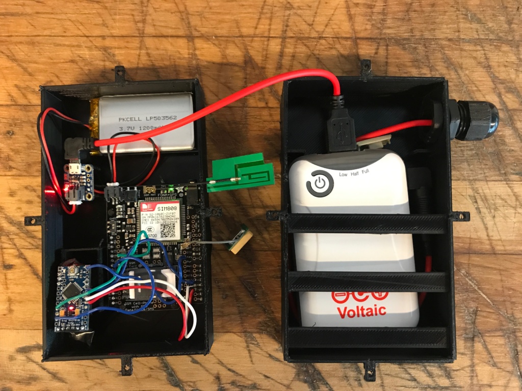
You can access the design on the Sketchfab link at https://skfb.ly/6qSZq or Github and download the STL files. By zooming in the case, you can visualize the Voltaic V15 battery pack on the top and the Arduino, GPS/GSM board, charger, and LiPo battery on the lower half.
Here is detail of the posts in the case designed to hold each component including the battery.
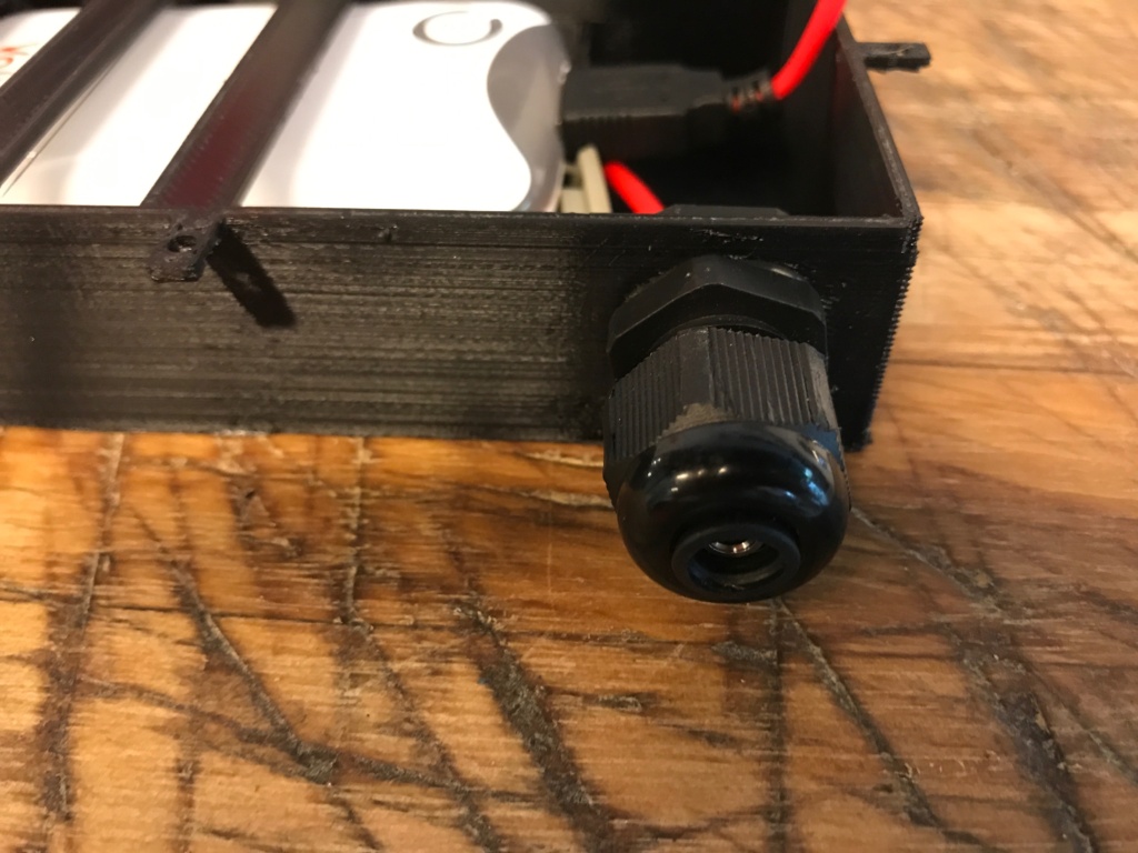
A hole in the case accomodates a PG13.5 gland. This allows us to make a waterproof connection from the solar panel to the Voltaic battery inside the case.
Hardware:
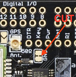
Start by cutting the thin metal trace between the two larger pads of the GND pin on the FONA board. Make sure to scrape it away using an XActo knife or any other sharp metal tool. By doing this, you will be able to wake/sleep the FONA board.
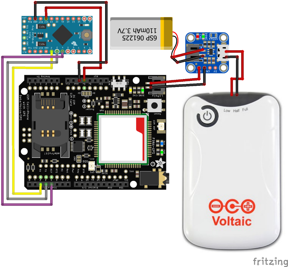
Next, refer to the Fritzing diagram below and make the proper electronic connections.
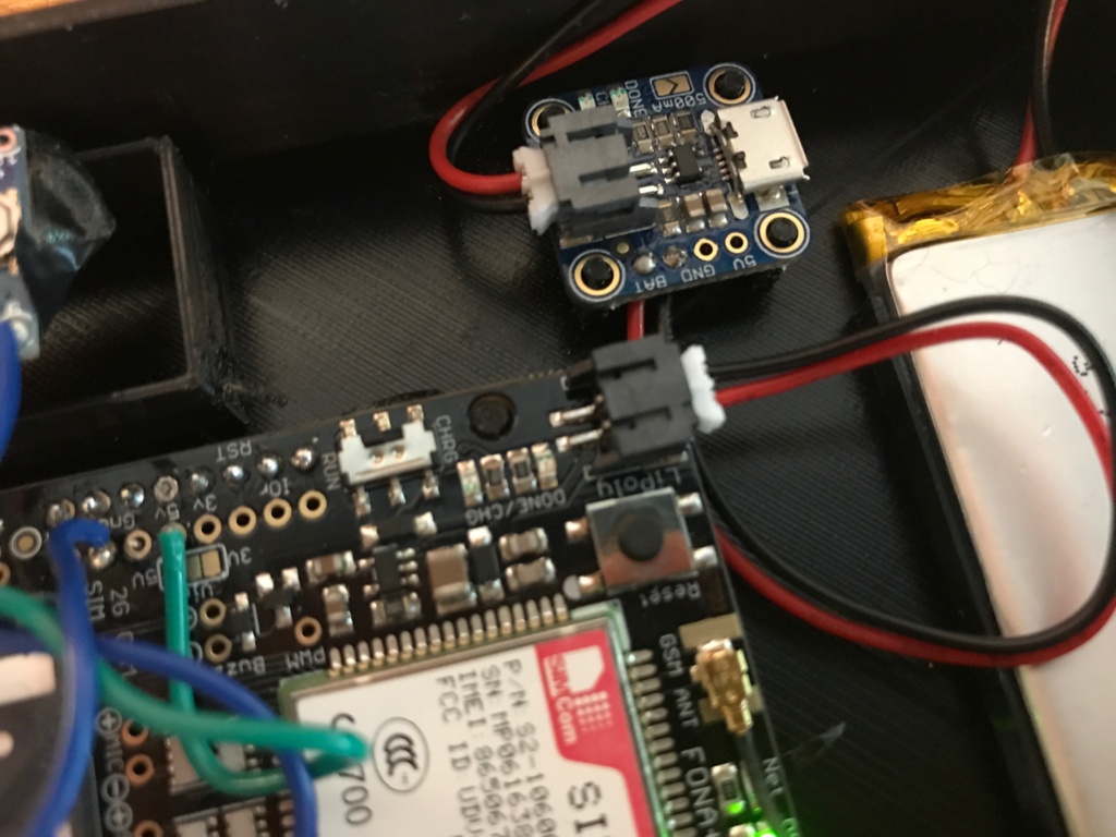
This is what the components will look like inside the case.
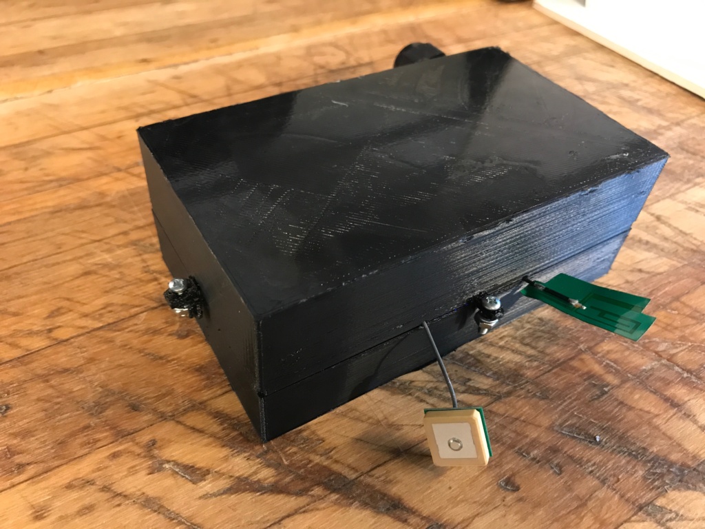
The completed case with components looks like this.
Notice that the LiPo battery is the primary power source for the FONA and Arduino board. The V15 battery keeps that topped up. Also, make sure to manually switch the button on the FONA board from charge to power mode. Lastly, properly install the SIM card (we used Ting from the Adafruit site) as well as both the GSM and GPS antennas.
Software:
For the coding part, we should acquire a location every 30 minutes (timeout 1minute), upload the data to the server, and put Arduino in deep sleep between transmission. Failure might occur while acquiring or uploading a location to the server thus we should always monitor the process by providing an override software reset in every step of the code. Preventing a failure using the out of the shelf Arduino Pro Mini is not possible therefore we need to bootload the Arduino with a different software “Optiboot”. Follow the first 4 steps to flash Optiboot and then Upload the Code to your Arduino.
Step 1: Upload the ArduinoISP code located under Examples to the Arduino Uno.
Step 2: Install Optiboot by following the instructions at this GitHub Link: https://github.com/Optiboot/optiboot under “To install the Arduino software”.
Step 3: Connect your Arduino Pro Mini to an Arduino Uno acting as an ISP programmer by referring to the Fritzing diagram below.
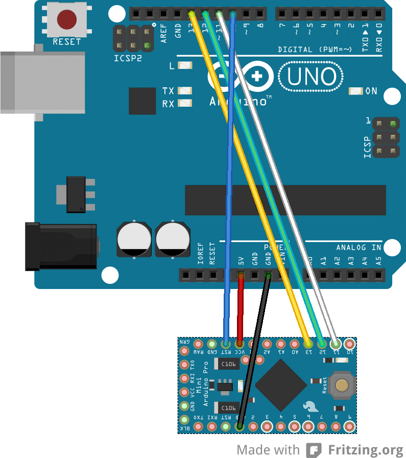
Step 4: Under tools select “Optiboot on 32-pin cpus”, “ATmega328”, “16MHz”, “Arduino as ISP” and flash the bootloader by selecting “Burn Bootloader”.
Step 5: Disconnect the Arduino Pro Mini from the Arduino Pro Uno.
Step 6: Connect your Arduino Pro Mini to the PC via the USB to TTL Cable.
Step 7: Access the Arduino code from GitHub at https://github.com/VoltaicEngineering/Solar-Bicycle-Tracker and modify the code by customizing “yourthing” variable.
Step 8: Upload the modified code to your Arduino Pro Mini.
System Power Consumption:
The Arduino Pro Mini is consuming only 23 μA while in sleep mode and a maximum of 20mA with peaks of 2A while acquiring a location. We believe that the system can run for at least a week without any solar charge.
Data Presentation/Server Side:
We are uploading the location to a Dweet server and we would like to graphically display it on the Freeboard website. Access Freeboard.io, create an account and follow the instructions to customize your dashboard.
Step 1: Create a new panel and give it a name (example: Solar Bicycle Track).
Step 2: Access the newly created panel and select “ADD” under Datasources.
Step 3: Select the Dweet.io as a type of Datasource and enter the modified “yourthing” from the Arduino code in the THING NAME.
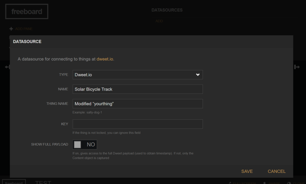
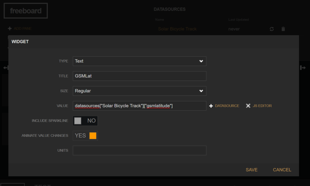
Step 4: Select “Add Pane” and start customizing your dashboard. Select different type of widgets and replace the [“gsmlatitude”] to any of these (“gsmlongitude”,” ti” referring to time,” da” referring to date,” gpslatitude”,” gpslongitude”, “batt” referring to battery % level) streamed by Arduino.
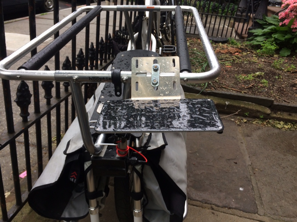
On the Bicycle
The Xtracycle has lots of nice mounting points for everything. On a traditional bike, we could see this going under a bike rack. Here, we use the hooptie to mount the panel and the cargo rack to hold the case.
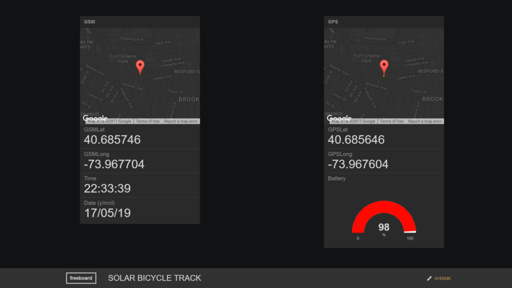
Tracking the Bicycle
Finally, watch the bike tracking device streaming on Freeboard: https://freeboard.io/board/nX82gJ. Or read more information on Voltaic Systems work powering remote IoT products.
About the Author: Karim Chamaa is a Mechatronics and Robotics Engineer. His portfolio can be found here.